Introduction:
Welcome to “The Practical Guide to Facility Piping System Schematics”. In this guide, we will explore the importance of accurate piping system schematics and provide practical guidance on creating, updating, and managing them effectively. Whether you are a facility manager, maintenance engineer, or aspiring professional in the field, this guide will equip you with the knowledge and tools to ensure your facility’s piping systems remain well-documented and easily navigable.
Download the PDF version of full guide HERE.

Section 1: Understanding Facility Piping System Schematics
The role and purpose of piping system schematics:
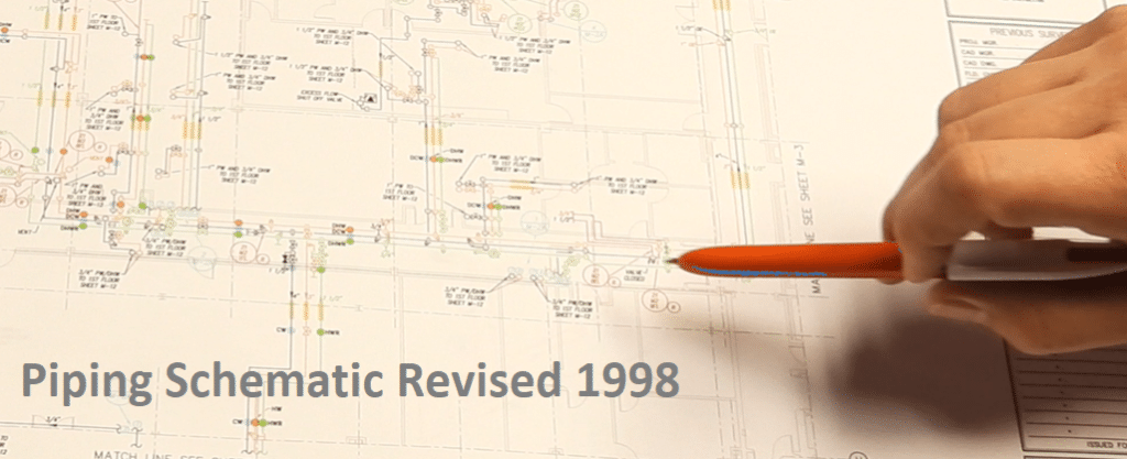
Piping system schematics play a vital role in facility management by providing a visual representation of the layout, connections, and components of a piping system. They serve as a blueprint that helps engineers, maintenance personnel, and operators understand the system’s design, functionality, and flow paths. Schematics enable efficient troubleshooting, maintenance planning, and modification of the system.
Example Schematics for Legionella Prevention at Hospital: HERE
Components of a piping system schematic:
A typical piping system schematic includes various components, such as pipes, valves, fittings, pumps, instruments, and control devices. Each component is represented by specific symbols and annotations that convey crucial information about its size, material, flow direction, and other relevant details. The schematic also illustrates the connections between components, including branch lines, tees, reducers, and unions, allowing for a comprehensive understanding of the system’s configuration.
Common symbols and abbreviations used in schematics:
To ensure universal understanding, piping system schematics employ a standardized set of symbols and abbreviations. Some commonly used symbols include circles for pumps, squares for valves, rectangles for tanks, and triangles for instruments. Additionally, abbreviations are used to represent specific materials, measurements, or operational parameters. Familiarizing yourself with these symbols and abbreviations is essential for accurately interpreting and creating piping system schematics.

Guide Section 2: Creating and Documenting Piping System Schematics
Steps to creating accurate schematics:
Creating accurate piping system schematics involves several key steps:
Step 1: Gather relevant information about the system, including design drawings, equipment specifications, and any existing piping schematics or floor plan drawing.
Step 2: Perform a thorough field survey to verify the actual installation and collect data on pipe sizes, existing and necessary labeling, fittings, and interconnection locations. This information is then used to create the initial schematic using CAD or similar systems. Visually surveying actual piping systems and reporting out on conditions and configurations is the Only Way to capture a complete assessment; watch this short explainer video about The Only Way HERE
Step 3: Insert the surveyed information into a piping schematic layout that resembles or closely matches the actual top-down view of the piping system. Using multiple layers and scalable views within a CAD program can allow for a high level of detail in the piping schematic. Where necessary, isometric views can be used to convey complex piping configurations.
Continue reading this free guide HERE
Guide Summary:
Maintaining accurate and up-to-date piping system schematics is crucial for the efficient operation and maintenance of facilities. By following the guidance and best practices outlined in this e-book, you will be well-equipped to create, update, and manage your facility’s piping system schematics effectively. Remember, a well-documented schematic is not only an asset, but also an essential tool for troubleshooting, problem-solving, and ensuring the longevity of your facility’s piping systems.
For solutions and quotes on piping surveys and schematics, talk to a HydroCorp Schematic Expert HERE

