Poll Summary
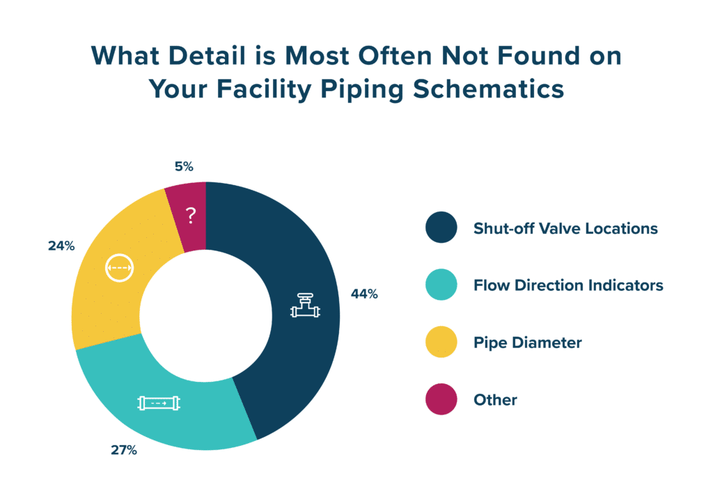
In a December 2023 poll of 210 Healthcare Facility Professionals, results indicate a surprising data pattern worth noting in Hospital maintenance planning. When asked what detail is most often missing on their facility piping schematics (of medical gas, water, process fluids, and fire suppression systems, etc.) the most common response, with 44% of the vote, was “Shut-Off Valve Locations”. This option beat out “Flow Direction Indicators” with 27%, “Pipe Diameter” with 24%, or “Other” with 5%. The reason this result is so surprising is the critical nature of shut off valves.

Having reliable knowledge of precise locations of all shut-off valves of all systems is always vital in any facility. However, a healthcare facility’s high stakes conditions means that information and knowledge could be the difference between life and death. This also applies to knowledge on Flow Direction and Pipe Diameters, with each of these pieces of information making up the whole picture of the current conditions of a healthcare facility’s piping systems.
Poll Result #1: Shut-off Valve Locations (Not Found on 44% of Piping Schematics)
Shut-off valves are among the most critical details recorded on healthcare facility piping schematics, and their proper location documentation is a lifeline for basic maintenance, piping system failure response and system expansion planning. System Outages and life-threatening situations that could emerge without properly documented shut-off valve locations recorded on piping schematics of three systems: Medical Gas, Potable Water, and Fire Suppression.

Medical Gas Systems: The importance of shut-off valves in this context cannot be overstated. These valves allow facility staff to isolate specific sections of the gas supply quickly in case of emergencies, routine maintenance, or repairs. In the event of a gas leak or malfunction, immediate action is crucial to prevent potential harm to patients and staff.
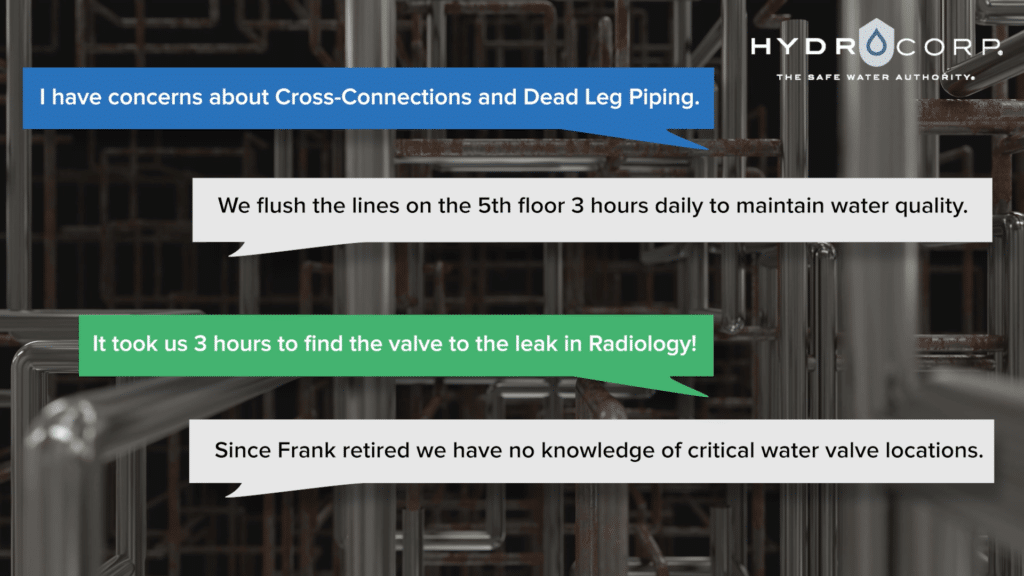
Water Supply Systems: Shut-off valves play a pivotal role in regulating and controlling water flow throughout the building. This not only safeguards the equipment but also minimizes the risk of water damage to sensitive medical instruments and electronics. These valves’ usefulness depends on the ability to identify the correct valve to close or open to control or stop the flow of water to specific areas of the facility. Without the shut-off valves properly and accurately documented on the piping schematics to lead maintenance personnel to the correct shut-off valve, it could take hours to locate a leak with trial-by-error valve closures.
Fire Protection Systems: Fire safety is a top priority in any building, but in a healthcare setting where patient vulnerability is high, it takes on added significance. Properly functioning shut-off valves ensure that the fire protection system remains reliable and responsive. Knowing where those valves are located and being able to reach them in a timely manner could make all the difference in the case of a fire emergency.
Poll Result #2: Flow Direction Labels/Indicators (Not Found on 27% of Piping Schematics)
Flow direction indicators on healthcare facility piping schematics are crucial for several reasons, as they play a vital role in ensuring the safety, efficiency, and proper functioning of the facility’s infrastructure. Indicators help prevent errors during maintenance activities, reducing the risk of mistakenly disrupting critical services or causing unintended cross-connections. Aside from regulatory compliance requirements, here are some key reasons why these indicators are important:

Medical Gas Systems: In healthcare facilities, the correct flow of medical gases and fluids is essential for patient safety. Flow direction indicators provide visual cues to medical staff, ensuring that they are aware of the intended direction of flow for critical substances such as oxygen, nitrogen, and other medical gases. Proper identification of flow direction helps prevent accidental misconnections or errors in the administration of medical gases, which can have severe consequences for patient health and safety. Having a bird’s-eye-view of the flow directions of the various medical gas systems on their piping schematics empowers facility managers to quickly assess where potential issues could arise and prevent any misconnections.
Water Supply Systems: Healthcare facilities have a variety of water systems, including potable water, process water, and sterile water. Flow direction indicators help indicate the intended direction the fluid is traveling to. Having clear indicators ensures that water meant for non-potable purposes, such as cooling systems or equipment cleaning, does not accidentally mix with the potable water supply.
Fire Protection Systems: Flow direction indicators on piping schematics of fire suppression systems are important for ensuring swift and accurate response during emergencies. These indicators guide firefighters and maintenance personnel, clearly illustrating the intended direction of water or suppressant flow. By providing a visual roadmap on the piping schematics, these indicators enhance operational efficiency, reduce response times, and contribute to overall safety.
Poll Result #3: Pipe Diameter (Not Found on 24% of Piping Schematics)
In healthcare facilities, the inclusion of pipe diameter information on schematics for medical gas systems, potable water systems, and fire suppression systems is indispensable for operational efficiency, regulatory compliance, and the overall safety of patients and staff.

Medical Gas Systems: Understanding pipe diameters is crucial to ensuring the proper flow of gases to patient care areas. Different medical applications may require varying gas volumes. It also aids in preventing issues like pressure drops that could compromise the delivery of life-sustaining gases. Having this crucial information readily available on piping schematics makes the installation of any new equipment easier and helps ensure that the proper volumes of gases are readily available for patients.
Water Supply Systems: In potable water systems, pipe diameter information is essential for maintaining adequate water pressure throughout the facility. Proper pressure is vital for ensuring the reliable supply of water to various departments, including patient rooms, surgical suites, and sanitation areas. Inadequate pressure can result in diminished water quality, reduced functionality of medical equipment, and inconvenience for both patients and staff. When there is an expansion of the facility or a certain wing of the building is repurposed, being able to supply construction or installation crews with up to date piping schematics with indications of the pipe diameters is essential.
Fire Protection Systems: Fire suppression systems rely on the appropriate pipe diameter to deliver sufficient water or suppressant to control and extinguish fires effectively. Insufficient pipe diameter can compromise the system’s ability to respond promptly in emergency situations, potentially leading to increased property damage and risk to life. Not having as-installed information regarding the pipe diameters of a facility’s fire suppression system could spell disaster
Poll Result #4: Other Responses (Not Found on 5% of Piping Schematics)
While “Other” only accounted for 5% of the poll voting, one specific piece of critical information that was indicated missing on piping schematics was Temperature Control Valves, or TCVs. Clearly noting temperature control valve locations on piping schematics for potable water systems is crucial facility operation, maintenance access and documentation. These valves regulate water temperatures to prevent scalding or exposure to waterborne pathogens. Accurate documentation ensures that healthcare staff can quickly identify, locate, and access these valves for maintenance, adjustments, or emergency responses. In healthcare settings, where vulnerable patients are present, safe temperature control is paramount to avoid injuries and infections. Properly labeled valve locations enable healthcare facilities to provide a secure and comfortable environment while adhering to regulatory standards and best practices.

Take-Aways:
The surprising results of this poll indicate two things: one, that the most common missing component on healthcare facility piping schematics is the location of shut off valves and two, there are many critical, potentially life-saving aspects of multiple piping systems that are simply undocumented. Whether it is shut off valves, flow direction indicators, pipe diameter, or TCVs, missing any of this essential information can only set up a facility for a potential disaster. Not being able to quickly locate these components in an emergency or not being able to supply a contractor with up-to-date information could lead to catastrophe.
The Only Way:
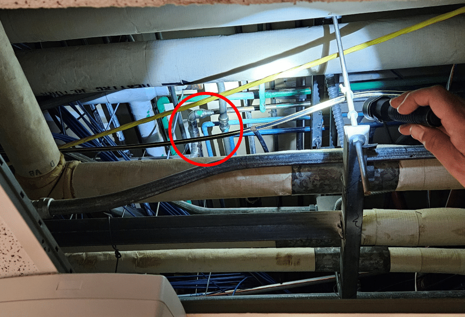
Whether it’s the medical gas system, potable water plumbing or fire suppression, the only way to gather and compile all the critical data needed to generate up to date and accurate piping schematics is the meticulous method of visually tracing every inch of piping in a specific system; from its initial source, above hallways and rooms, to each end point use. This means: climbing ladders, lifting ceiling tiles, inventorying all related valves, labels, and connections, and rendering field drawings of the piping system being surveyed. The more information that piping schematics can provide, the more control over the mitigation of risks can be placed into the hands of facility managers and administrators.

